Installing automatic bollards is not like installing a fence post. Get the foundation wrong and the bollard will not stop what it is supposed to stop. Get the drainage wrong and you will be replacing corroded components within two years. Get the wiring wrong and the bollard simply will not work — or worse, it will work intermittently, failing exactly when you need it.
This guide covers the three things that determine whether a bollard installation succeeds or fails: foundation design, water management, and electrical connections. It is based on real installation data from multiple manufacturers, including GS Automatic's published installation steps and field experience with both hydraulic and electromechanical systems.

Step 1: Foundation excavation — how deep and how wide
The foundation is the single most important part of the installation. A crash-rated bollard that stops a 7.5-ton truck at 80 km/h does so by transferring impact energy into the ground through its foundation. If the foundation is undersized, the bollard will rip out of the ground regardless of its rating.
Foundation dimensions depend on the bollard type:
High-security hydraulic bollards (K12/M50 rated): These need the deepest foundations. GS Automatic specifies approximately 800 mm excavation depth and a total underground cylinder depth of 1,150 mm for the GS600. The underground diameter is 325 mm for the cylinder housing, but the concrete foundation around it is larger — typically 600 to 800 mm in diameter — to provide enough mass to resist impact forces. At these depths, you are almost certainly going to encounter underground utilities in urban areas. Plan for utility locating before you dig.
Mid-range automatic bollards (K4 to K8): Foundation depth is typically 600 to 900 mm. The cylinder underground depth is less, and the concrete volume is proportionally smaller. These are easier to install in retrofit situations where deep excavation is impractical.
Anti-vandalism and urban bollards: Foundations of 300 to 600 mm are common. Some surface-mounted models bolt directly to existing concrete with no excavation at all. These are not designed for vehicle impact beyond low-speed collisions, so the foundation requirements are driven by stability, not crash resistance.
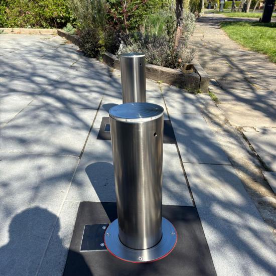
Fixed and removable bollards: Fixed bollards set in concrete foundations similar to light posts — 300 to 600 mm deep, with the bollard embedded directly in the concrete. Removable bollards use a ground socket: a steel sleeve set in concrete that the bollard slides into. The socket must be installed perfectly vertical with the top flange precisely at ground level. A socket that is tilted by even a few degrees will make the bollard difficult to insert and remove.
A practical note: always dig wider than the specification minimum. The extra concrete volume costs little and significantly improves impact resistance. If the spec says 600 mm diameter, dig 700 mm. The marginal cost is a few bags of concrete. The benefit is a foundation that performs better than its rating.
Step 2: Drainage — when you need it and when you do not
Water is the enemy of underground electrical equipment. Every bollard installation needs some form of water management. The type depends on the bollard's power system and waterproof rating.
For 220V/380V hydraulic bollards, active drainage is required. GS Automatic's installation guide shows a dedicated drainage pipe running from the foundation base to a discharge point. The bottom of the excavation is filled with 20 to 30 mm pebbles and sand as a water seepage layer. A sump pump may be needed if the site has a high water table or the discharge point is above the foundation level. This drainage system adds cost and complexity: trenching for the drain pipe, grading for gravity flow or pump installation, and ongoing maintenance to keep drains clear. In heavy rain or flood conditions, a clogged drain means water accumulates around high-voltage electrical components — a serious safety risk.
For 36V DC electromechanical bollards with IP68 rating, drainage can be passive or eliminated entirely. IP68 means the bollard is rated for continuous immersion in water. The 36V DC power supply eliminates the electrocution risk even if the foundation pit floods. In these systems, a simple gravel bed at the bottom of the excavation provides enough drainage for normal groundwater. No drain pipes. No sump pump. No ongoing drain maintenance. This is one of the most significant advantages of 36V electromechanical systems, especially at sites with high water tables, coastal locations, or monsoon-prone regions.
Regardless of drainage method, every installation should include a gravel or crushed stone base layer of 150 to 200 mm at the bottom of the excavation. This prevents the bollard foundation from sitting directly on soil that can shift and settle. Compact the gravel before pouring concrete.
Step 3: Wiring and conduit — getting power and control to the bollard
Wiring requirements vary dramatically between hydraulic and electromechanical systems.
Hydraulic bollards need power wiring from the main electrical panel to the hydraulic power unit, plus control wiring from the power unit to each bollard. The power wiring carries 220V or 380V AC and must be in approved conduit buried at the required depth per local electrical code — typically 450 to 600 mm below grade. The hydraulic lines between the power unit and the bollards add another layer of buried infrastructure. GS Automatic's installation guide notes that each wire should be secured by waterproof tape to prevent water vapor from entering the wiring — a manual step that, if skipped, leads to corrosion inside the conduit.
Electromechanical bollards have simpler wiring. Each bollard gets a power and control cable, typically running from a central control cabinet. With 36V DC systems, the wiring falls under low-voltage regulations in most jurisdictions — simpler permits, less stringent conduit requirements, and safer for the installation crew. The cable run is also simpler: one cable per bollard, no hydraulic lines.
Common wiring mistakes: running cables through the same conduit as power lines (causes interference), failing to leave a service loop of extra cable at each bollard (makes future repairs impossible without re-trenching), and not labeling cables at both ends (turns troubleshooting into guesswork). Leave at least 500 mm of slack cable coiled inside each bollard's access compartment. Future you — or the maintenance crew — will be grateful.
Step 4: Concrete pour and curing
Use concrete rated for exterior in-ground applications — typically C25/30 or higher compressive strength. The concrete should be poured in a single continuous pour to avoid cold joints, which create weak planes in the foundation. Vibrate the concrete during pouring to eliminate air pockets and ensure complete compaction around the bollard housing.
Curing time matters. Concrete reaches about 70% of its design strength in 7 days and full strength in 28 days under normal conditions. Do not test or operate automatic bollards before the concrete has cured for at least 7 days. Operating a bollard in uncured concrete can shift the foundation and permanently misalign the cylinder, causing binding and premature wear. GS Automatic specifies covering the bollard head during concrete pouring to prevent splatter — a small detail that shows up as rust and cosmetic damage if ignored.
Step 5: Testing and commissioning
After the concrete has cured, run the bollard through its full cycle at least 10 times. Check for smooth operation, unusual noise, or binding. Verify the raised height matches the specification — a bollard that stops 20 mm short of its rated height is not providing rated protection. Test the emergency lowering function if the bollard has one. Test the control system integration: RFID readers, loop detectors, remote controls, and any integration with security management platforms.
A final checklist: foundation matches spec dimensions, drainage is functioning (pour water into the excavation and verify it drains), all electrical connections are tight and waterproofed, the bollard operates smoothly across full cycles, emergency functions work, and the site is cleaned up — concrete splatter removed, ground surface restored, and the bollard finish inspected for damage during installation.
For product-specific installation guidance, see Automatic Bollards and Fixed Bollards. Contact us for installation support at UPARK.
call us :
+86 18206096507 e-mail : [email protected]


 ipv6 network supported